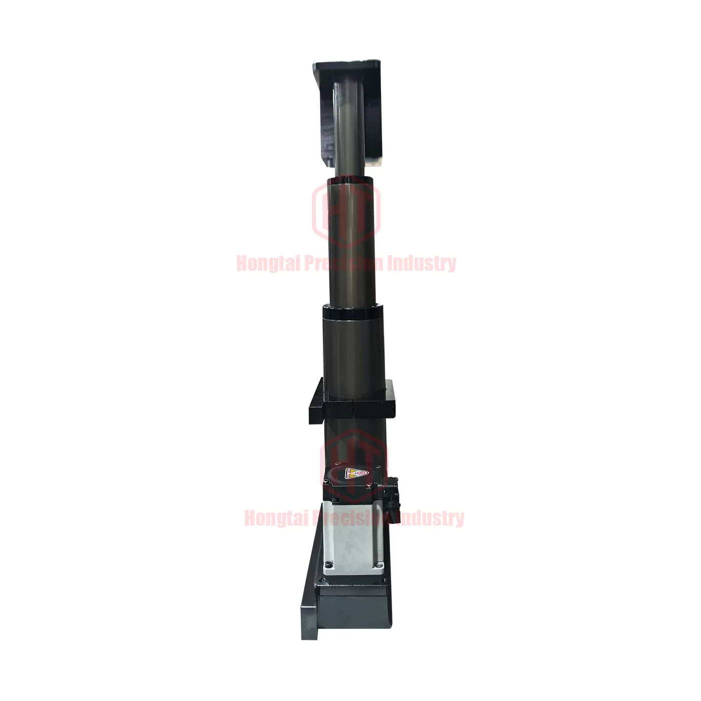
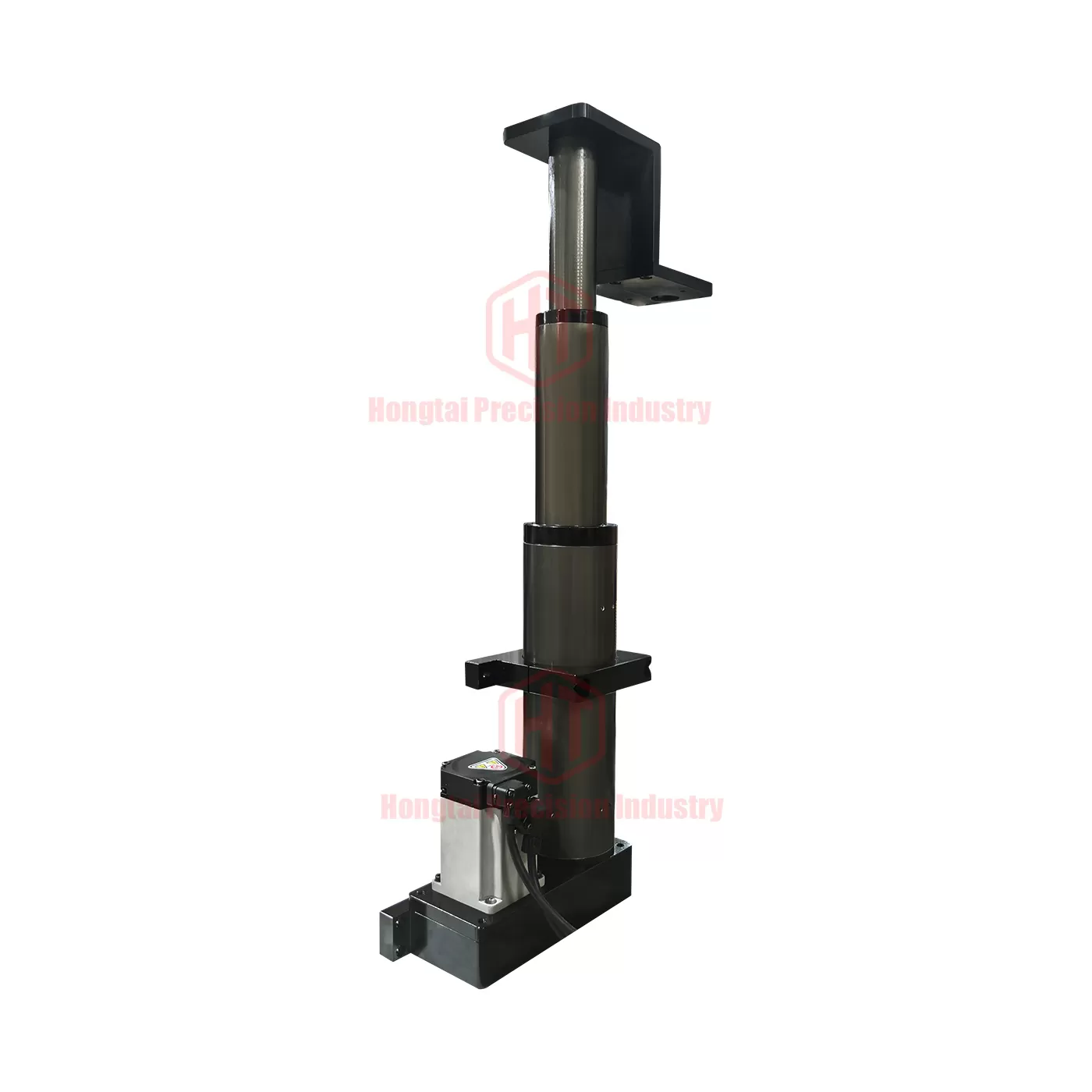
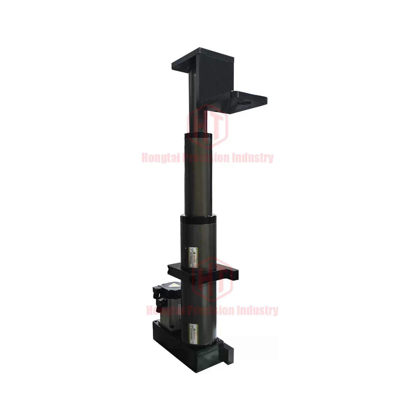
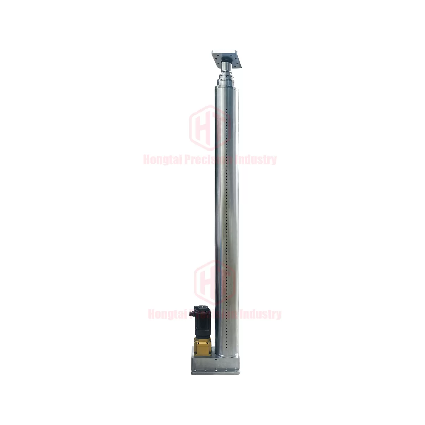
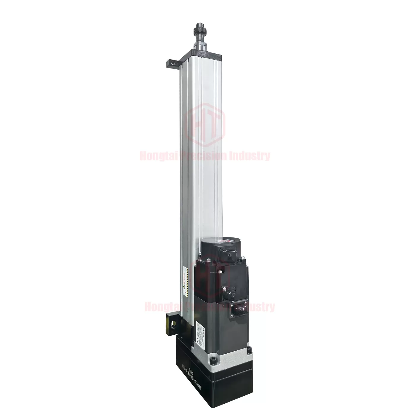
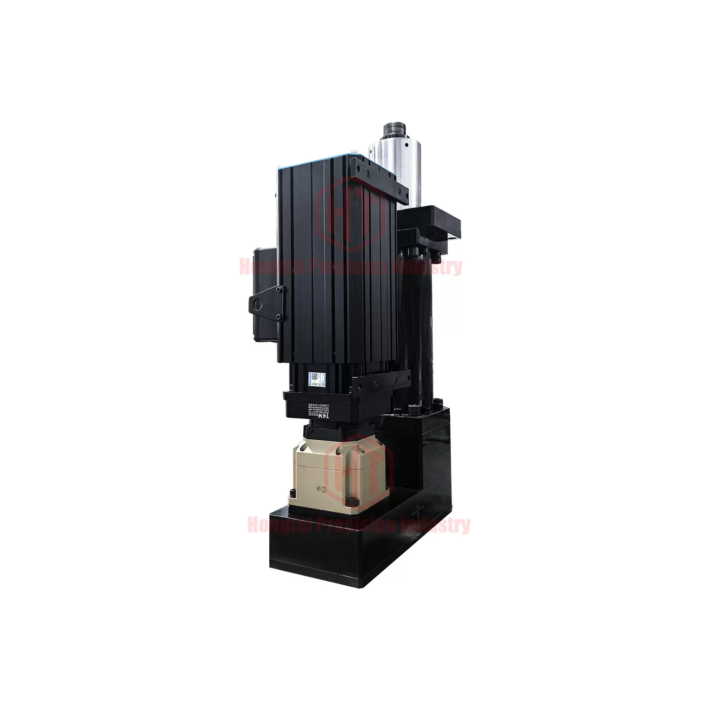
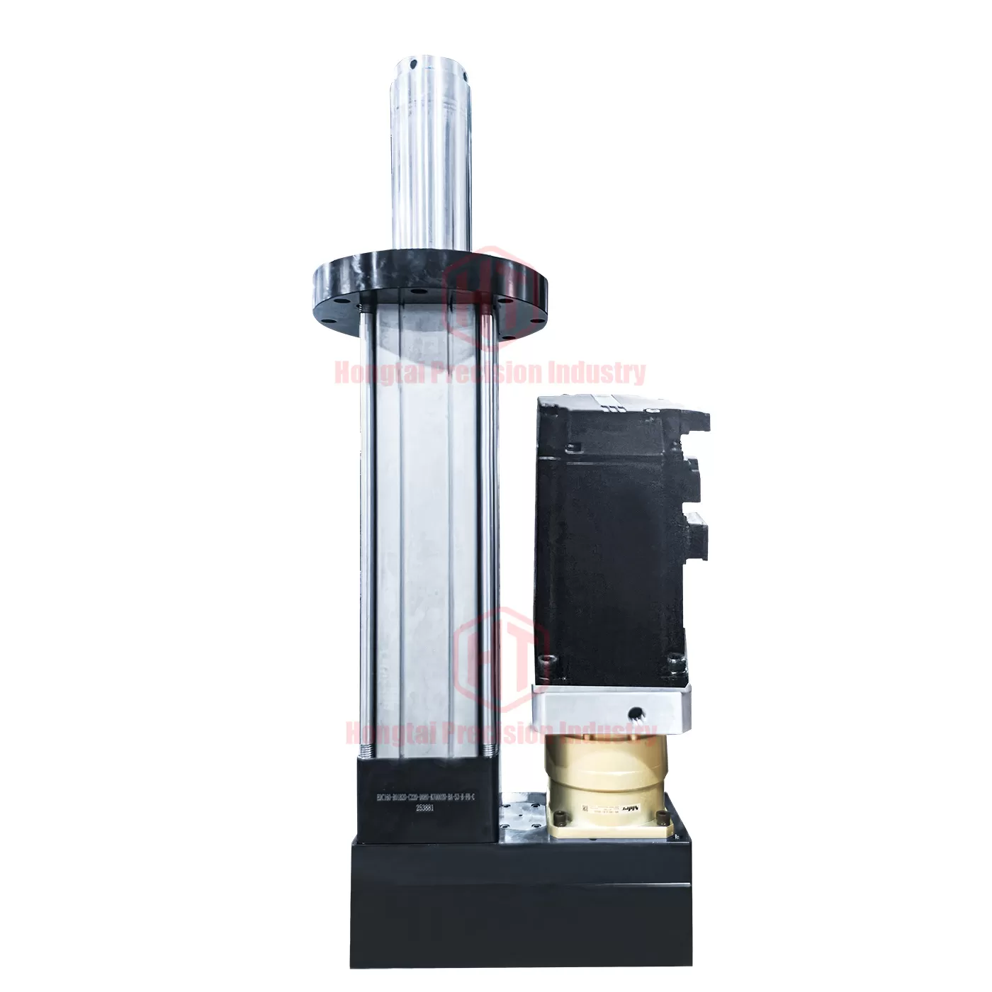
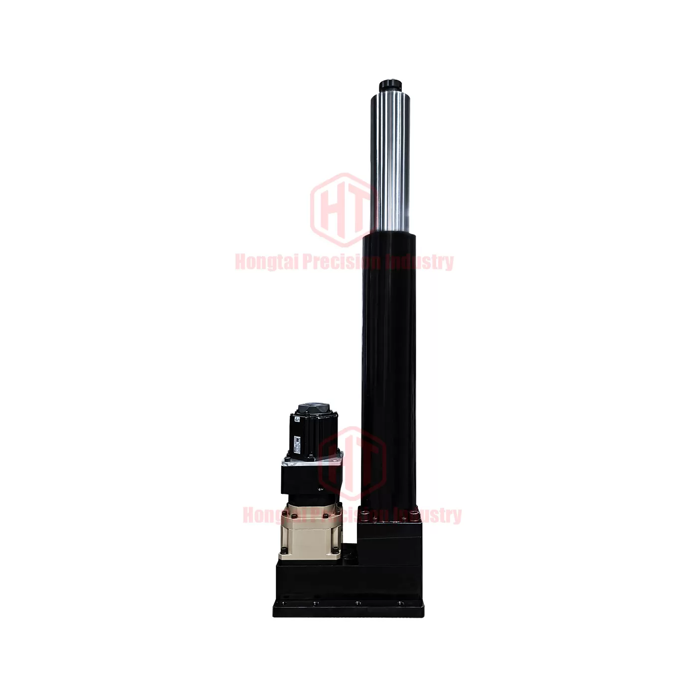
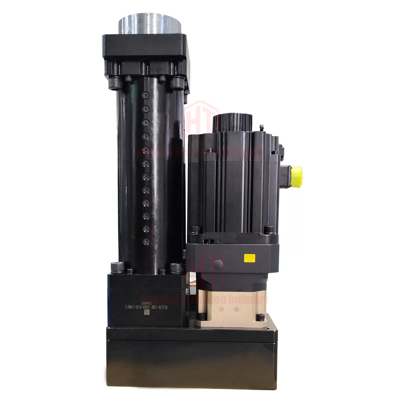
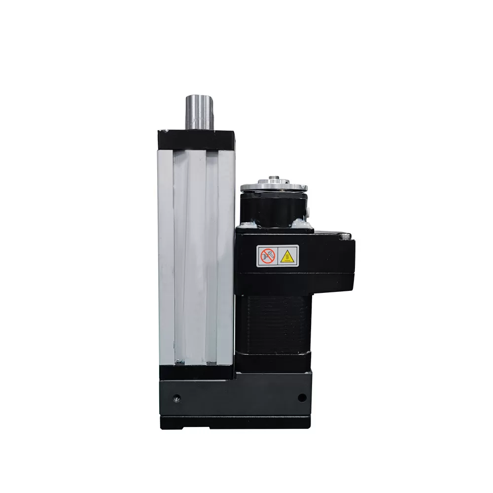
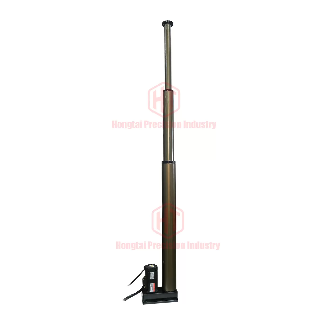
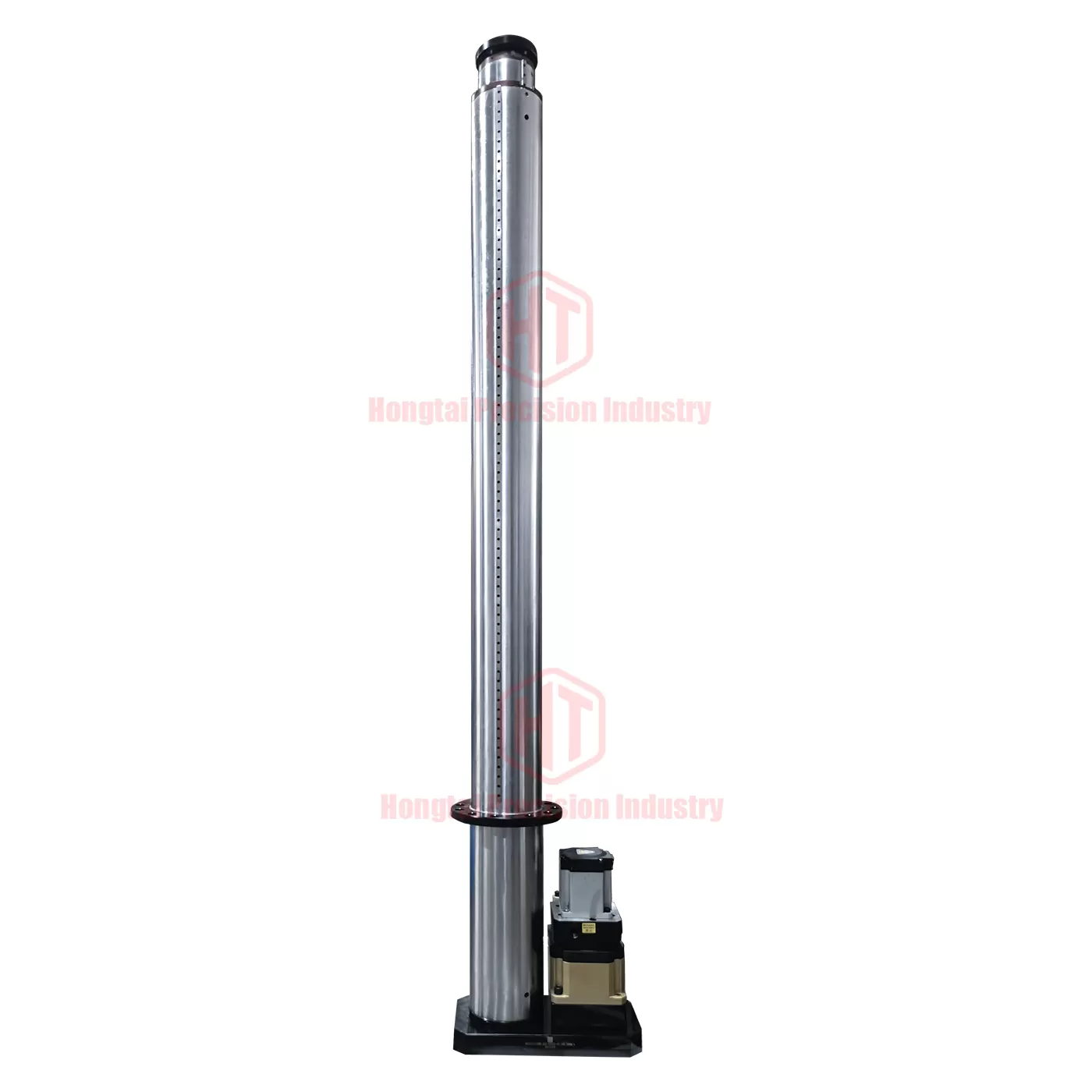
87 Multi‑stage Telescopic Electric Cylinder
Widely used in various industries, especially for Z‑axis lifting columns of manipulators.Capable of lifting and horizontal movement, featuring high precision, fast speed, large load capacity and long stroke.
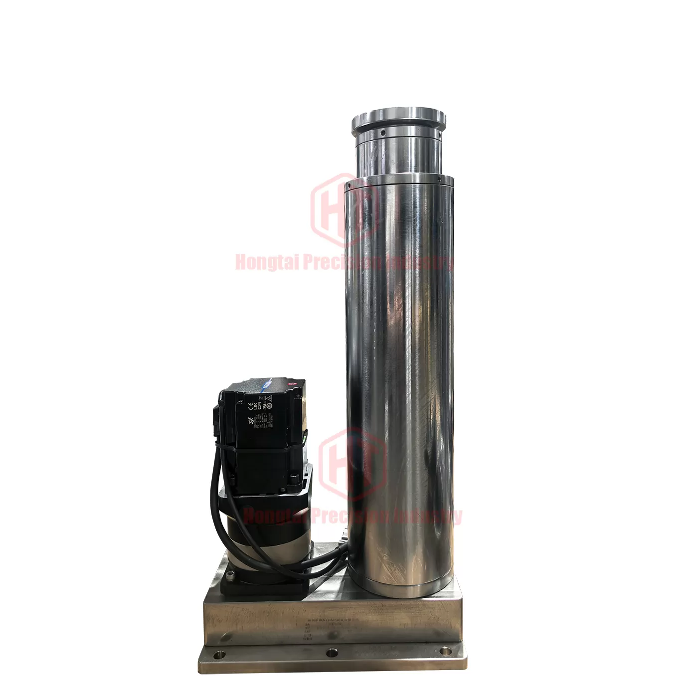
Model: RLD75
Lead: 10
Mounting: Multiple mounting options
Thrust/Load: Within 10 KN
Stroke: 0–1800 mm
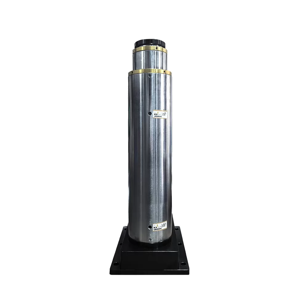
Material: Aluminum / Cylinder type
Speed: 0–200 mm/s
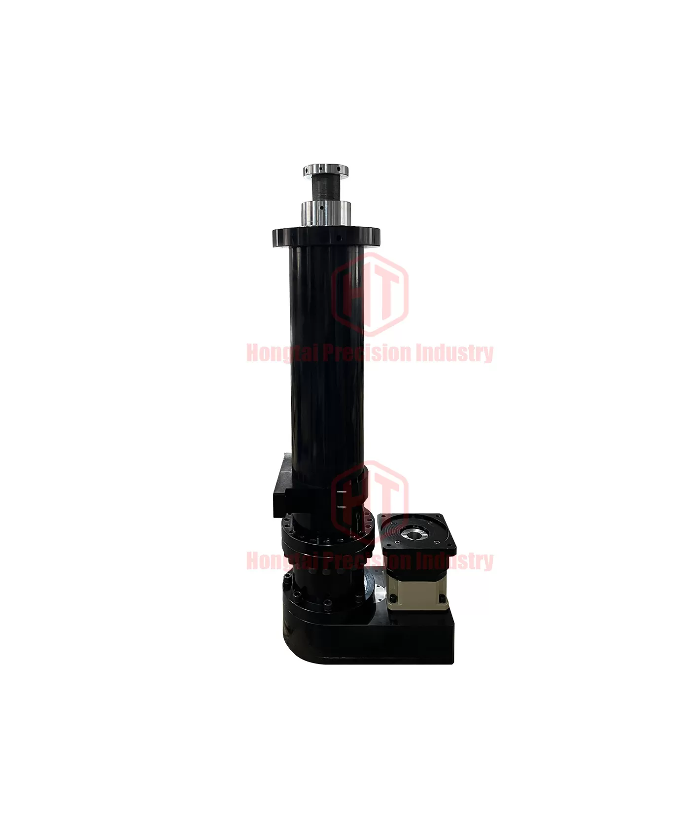
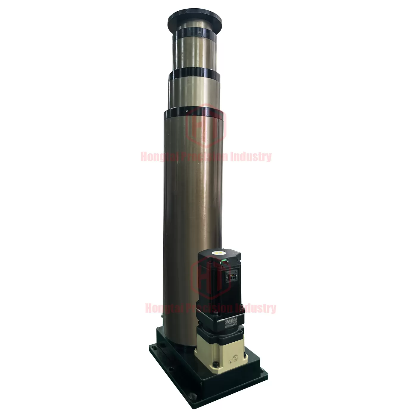
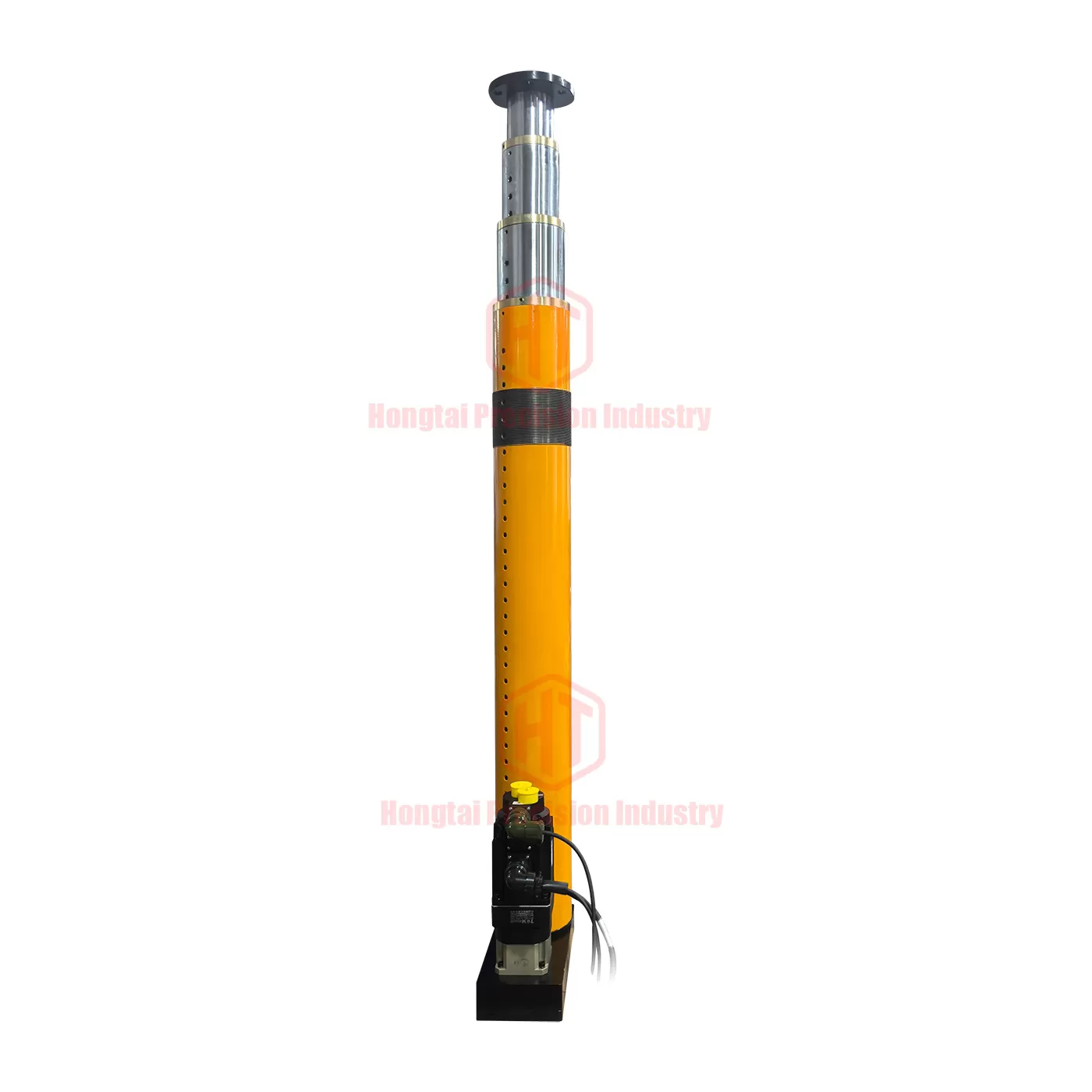
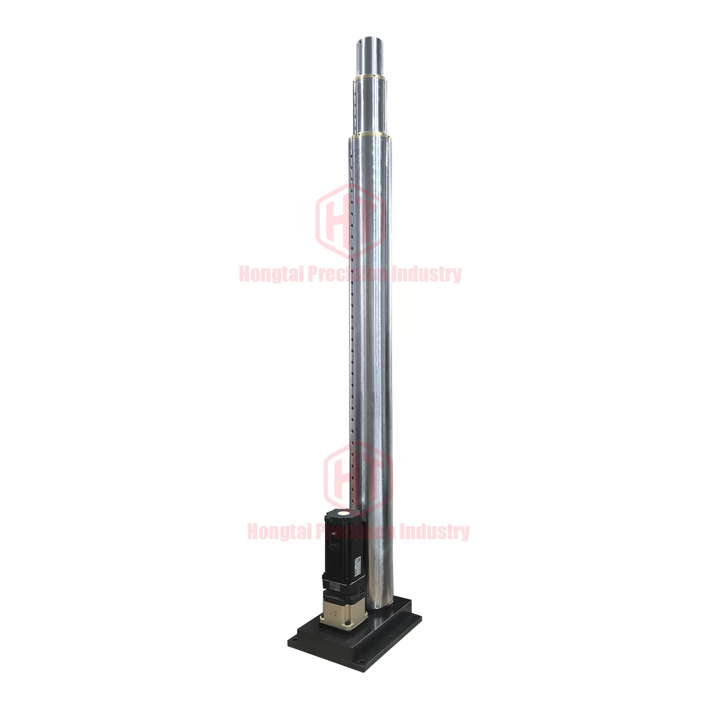
Multi‑stage Telescopic Electric Cylinder (Patented Product)
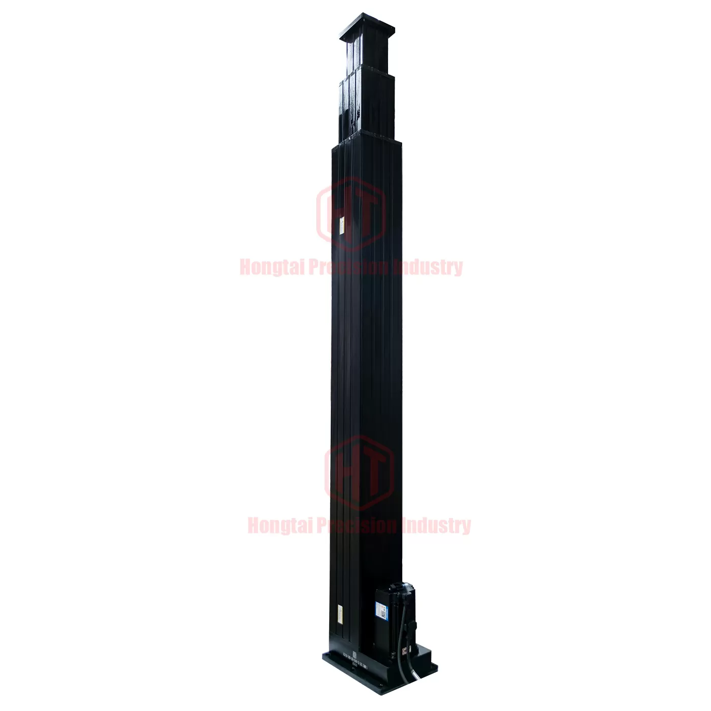
★ Customizable multi‑stage telescopic electric cylinders with stroke up to 20 meters and load capacity up to 20 tons.
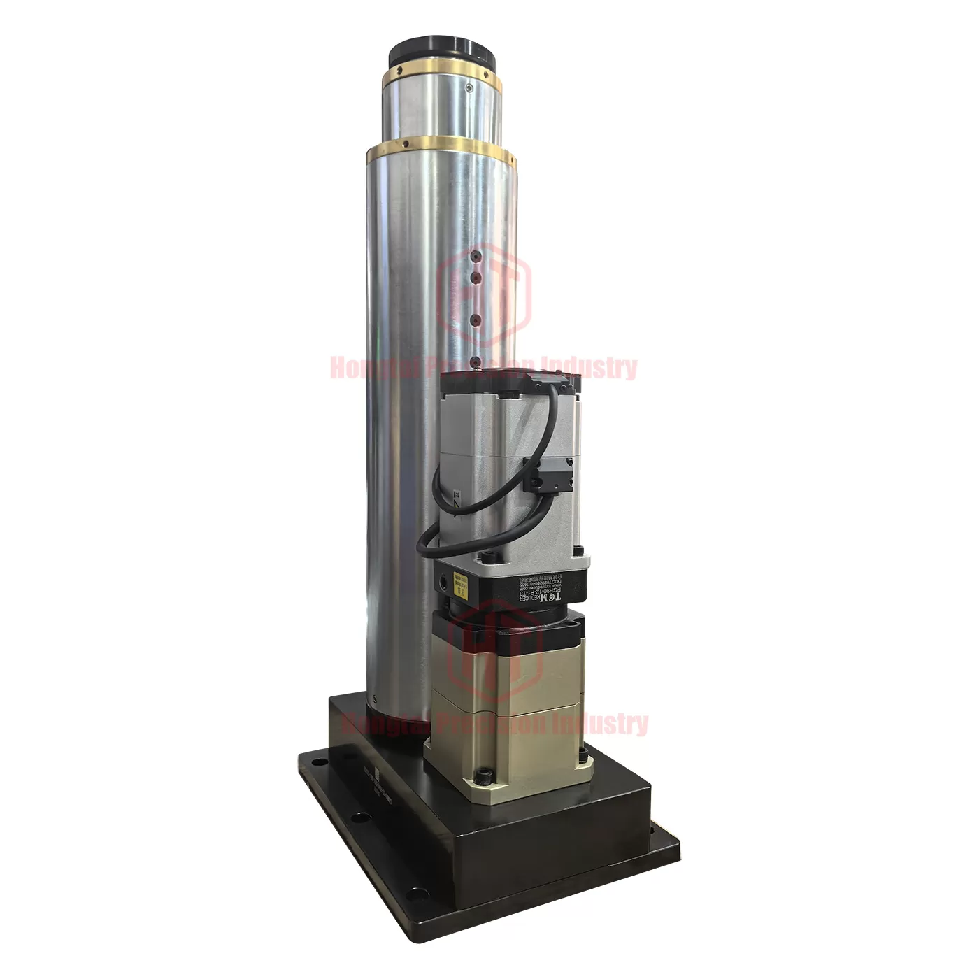
The multi‑stage telescopic electric cylinder is driven by a servo motor to rotate multiple ball screws, driving the screw pairs mounted on the pistons of multi‑section telescopic rods to achieve reciprocating linear motion.Compared with single‑stage servo electric cylinders, it features a simpler structure and excellent servo control performance, making it widely used in various industries.
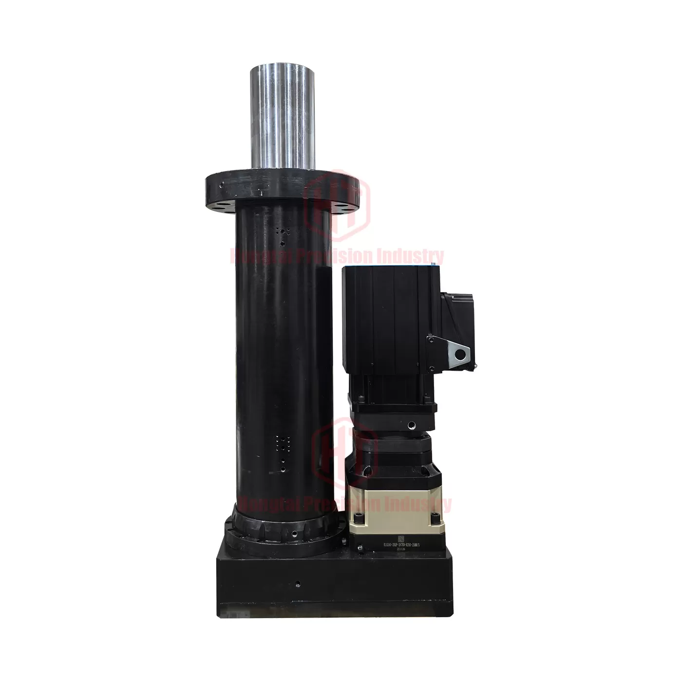
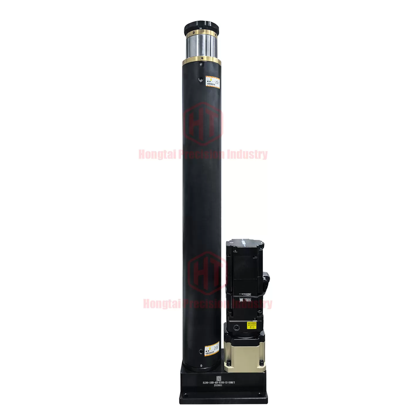
In actual production and manufacturing applications, there are often requirements such as limited installation space, long working stroke, or variable stroke during operation.Single‑stage electric cylinders can meet the requirement of small installation space, but cannot achieve long working stroke.
Multi‑stage telescopic electric cylinders are characterized by small installation space, long stroke, stable operation, high precision and controllability.
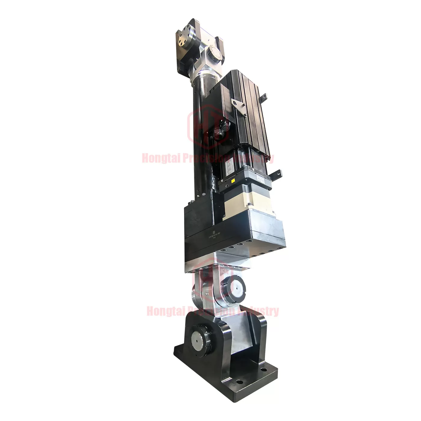
Our multi‑stage telescopic electric cylinders all adopt ball screws (higher transmission efficiency and higher precision than trapezoidal screws) as the transmission components.They can be designed with 3, 4, 5 or 6 telescopic sections including the main body.
They are widely applied in robots, automatic photography systems, transportation, inspection equipment, AGV logistics vehicles, automated equipment and other fields.